- 您现在的位置:买卖IC网 > Sheet目录325 > FAN7340MX (Fairchild Semiconductor)IC DVR BOOST SW LED BKLT 16-SOIC
�� �
�
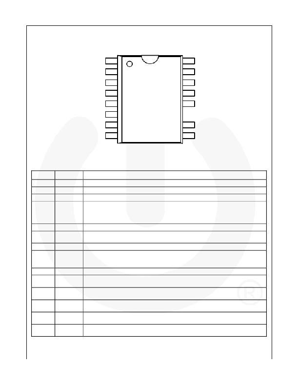
�Pin� Assignments�
�VCC�
�DRV�
�GND�
�CS�
�REF�
�FAULT�
�RT�
�SENSE�
�1�
�2�
�3�
�4�
�5�
�6�
�7�
�8�
�16�
�15�
�14�
�13�
�12�
�10�
�9�
�BDIM�
�ADIM�
�CMP�
�OVP�
�ENA�
�DRAIN�
�DRAIN�
�Figure� 2.� Package� Diagram�
�Pin� Definitions�
�Pin� #�
�1�
�2�
�3�
�4�
�5�
�6�
�7�
�8�
�9,� 10�
�12�
�13�
�14�
�15�
�16�
�Name�
�VCC�
�DRV�
�GND�
�CS�
�REF�
�FAULT�
�RT�
�SENSE�
�DRAIN�
�ENA�
�OVP�
�CMP�
�ADIM�
�BDIM�
�Description�
�This� pin� is� the� supply� voltage� of� the� IC.�
�This� pin� is� the� gate� drive� signal� of� the� boost� switch.�
�This� pin� is� the� ground� of� the� IC.�
�This� pin� is� for� sensing� the� current� flowing� through� an� external� MOSFET.� It� includes� a� built-in�
�300� ns� blanking� time.� The� peak� of� the� current� flowing� through� the� MOSFET� is� limited� to� this�
�pin� voltage.� Slope� compensation� of� the� boost� controller� can� be� programmed� through� the�
�series� resistor� of� this� pin.�
�This� pin� is� the� 5� V� reference� voltage� pin.� Maximum� current� capability� is� 3� mA.�
�This� pin� is� for� indicating� the� fault� signal.� This� pin� is� connected� to� the� open� drain.� When� OLP�
�protection� is� occurred,� the� FAULT� pin� is� pulled� HIGH.�
�Oscillator� frequency� set� of� the� boost� switch� (50� kHz� ~� 300� kHz).�
�This� pin� is� for� sensing� the� current� flowing� through� the� LEDs.� A� sensing� resistor� is� connected�
�from� this� pin� to� ground.� This� pin� is� connected� to� the� negative� input� of� the� internal� error�
�amplifier.�
�Drain� pin� of� PWM� dimming� power� MOSFET.�
�Enable� input� pin.� If� voltage� of� this� pin� is� higher� than� 1.22� V,� IC� is� starting� to� operate.� If� the�
�voltage� of� this� pin� is� lower� than� 1.15� V,� the� IC� stops� operating.�
�Over-voltage� protection� input� pin.� Output� voltage� of� the� boost� circuit� is� connected� to� this� pin�
�through� a� resistor� divider� circuit.� If� this� pin� voltage� is� higher� than� 3� V,� OVP� is� triggered.�
�This� pin� is� the� error� amplifier� output.� Typically,� a� compensation� capacitor� and� resistor� are�
�connected� to� this� pin� from� the� ground.�
�This� pin� is� for� setting� the� current� flowing� through� the� LEDs.� This� pin� is� connected� to� the�
�positive� inputs� of� the� internal� error� amplifier.� Linear� voltage� range� of� ADIM� is� 0.3� V~3.0� V.�
�This� pin� is� for� the� burst� dimming� signal.� If� this� pin� voltage� is� HIGH,� the� internal� dimming�
�MOSFET� is� turned� on.� If� this� pin� voltage� is� LOW,� the� dimming� MOSFET� is� turned� off.�
�Note� :�
�1.� Pin� 11� is� a� “� No� Connect� ”� pin� (not� shown� in� Figure� 2).�
�?� 2013� Fairchild� Semiconductor� Corporation�
�FAN7340� ?� 1.0.1�
�3�
�www.f� airchildsemi.com�
�发布紧急采购,3分钟左右您将得到回复。
相关PDF资料
FAN7346MX
IC LED DRVR 4 CHAN BLU 28SOIC
FAN73611MX
IC GATE DVR HIGH SIDE 1CH 8-SOIC
FAN7361MX
IC GATE DRIVER HIGH SIDE 8SOIC
FAN7362MX
IC GATE DRIVER HIGH SIDE 8SOP
FAN73711MX
IC GATE DVR HIGH SIDE 8-SOP
FAN7371MX
IC DRIVER GATE HIGH SIDE 8SOP
FAN7380MX
IC DRIVER GATE HALF BRIDGE 8SOIC
FAN7382M1X
IC GATE DRIVER HI/LO SIDE 14-SOP
相关代理商/技术参数
FAN7340MX-CUT TAPE
制造商:FAIRCHILD 功能描述:FAN7340 Series 35 V 250 mA LED Backlight Driving Boost Switch - SOIC-16
FAN7346
制造商:FAIRCHILD 制造商全称:Fairchild Semiconductor 功能描述:4 通道LED均流控制器
FAN7346M
功能描述:电流型 PWM 控制器 4Ch. LED Current control IC Lighting RoHS:否 制造商:Texas Instruments 开关频率:27 KHz 上升时间: 下降时间: 工作电源电压:6 V to 15 V 工作电源电流:1.5 mA 输出端数量:1 最大工作温度:+ 105 C 安装风格:SMD/SMT 封装 / 箱体:TSSOP-14
FAN7346MX
功能描述:LED照明驱动器 4Ch LED Curr Control IC for Lighting
RoHS:否 制造商:STMicroelectronics 输入电压:11.5 V to 23 V 工作频率: 最大电源电流:1.7 mA 输出电流: 最大工作温度: 安装风格:SMD/SMT 封装 / 箱体:SO-16N
FAN7346MX-CUT TAPE
制造商:FAIRCHILD 功能描述:FAN7346 Series 4 Channel LED Driver String Balancer w/ Dimming LED Load Control
FAN7361
制造商:FAIRCHILD 制造商全称:Fairchild Semiconductor 功能描述:High-Side Gate Driver
FAN7361_07
制造商:FAIRCHILD 制造商全称:Fairchild Semiconductor 功能描述:High-Side Gate Driver
FAN7361_09
制造商:FAIRCHILD 制造商全称:Fairchild Semiconductor 功能描述:High-Side Gate Driver